CISC836: Assignment 3
Queen's Logo

Beyond Code: An Introduction to Model-Driven Software Development (CISC 836, Fall 2021)

Assignment 3 (MDSD with RSARTE)

Due: Thursday, Nov 4

Intro

  1. Purpose of the Assignment:
    1. Give you practical experience with timed systems and fault-tolerance (in the context of UML-RT and RSARTE) (Part I).
    2. Illustrate how UML-RT's support for dynamic instance and connector creation can be used to increase the generality of an application (Part II).
  2. Preparation:
    1. The RSARTE installation that you used for Assignment 1 will also be used for this assignment.
    2. Make sure that you are aware of the design guidelines discussed in class.
    3. If questions come up, feel yourself encouraged to post them on the OnQ pages of the course.

Part I (40 points total)

  1. Problem Description:
    The problem is to sort a stream of parcels (or pieces of luggage) into 'bins' according to the destination of the parcel. The central piece of hardware to be used is a 'stage' which consists of two 'chutes', one 'sensor', and one 'switcher'. A parcel will enter the stage on one end and eventually emerge on the other end from one of two openings. To form a 'parcel router', stages are arranged in a binary tree-like fashion with the opening of one stage feeding parcels directly into either the entry of the next stage or a bin. The journey of a parcel through a stage proceeds as follows:
    1. After entering the stage, the parcel will travel down the first chute ('chute1'). The time required for the parcel to go from the beginning to the end of the first chute is called 'chute1Delay'.
    2. At the end of the first chute,
      • the parcel enters the second chute ('chute2'). The time required to travel down this chute is called 'chute2Delay'.
      • the destination of the parcel is read by the sensor which uses it to determine which one of the two openings the parcel is to exit the stage from. The sensor sends this direction information (given in terms of one of two values: 0 for 'left' and 1 for 'right') to the switcher which then positions its internal routing mechanism accordingly. The operation of the sensor and the positioning of the switcher is assumed to take neglible time.
    3. At the end of the second chute, the parcel will enter the switcher and emerge at one of the ends after 'switcherDelay' seconds. Any arrival of direction information from the sensor before the parcel leaves the switcher may change the opening the parcel emerges from. In other words, the direction information from the sensor can change the direction of the parcel up until the parcel has left the switcher.
    4. At the end of the switcher, the parcel will leave the stage and either enter the next stage or reach a bin.

  2. Description of provided UML-RT model:
    A simulation of a parcel routing system with 4 destination bins has been designed with UML-RT. The structure of this design closely mimicks that of the physical system and is shown below:

    Parcel router capsule diagram Stage capsule diagram

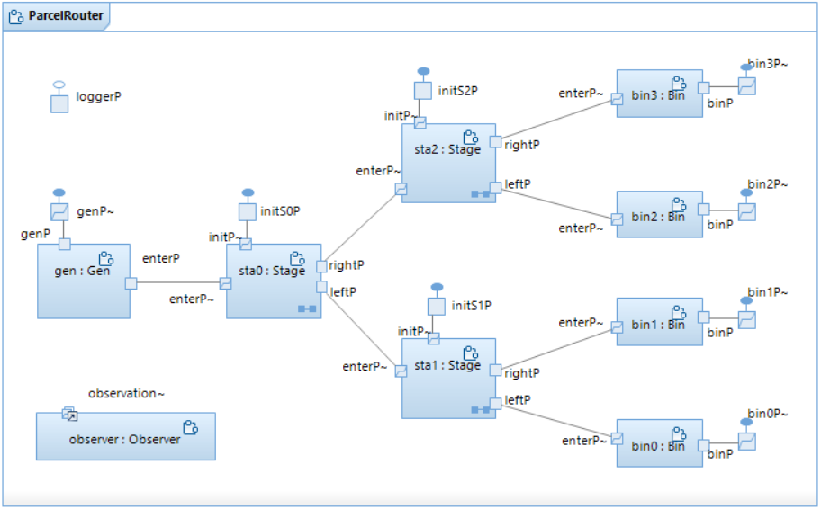
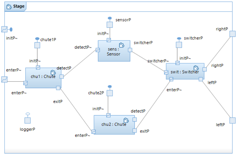
    As shown in the diagrams, the router consists of nine capsule instances on the top level, while each stage contains another four instances (so, the entire router consists of no less than 22 communicating state machines, resulting in more than 7K lines of generated C++ code!):


    For checking purposes, the parcel router contains 3 attributes in which it counts the number of parcels generated for each destination ('generated:int[4]'), the number of parcels that arrived correctly at their destination ('arrived:int[4]'), and the number of parcels that got routed to the wrong bin ('erroneousArrivals').

    The state machine of the parcel router

    1. collects command line arguments (if any),
    2. sends intialization messages to the generator and the stages,
    3. waits for 'generated(dest)' messages from the generator and increments the appropriate counter,
    4. waits for 'arrived(dest)' messages from the bins, checks for incorrect routing, and then increments the appropriate counter,
    5. waits for the 'done' message from the generator, and then logs the total numbers of generated and arrived parcels before it terminates.

  3. How to invoke the simulation:
    The execution can be customized via 5 command line arguments

    >> ./Parcelrouter.exe -UARGS <numParcels> <genDelay> <chute1Delay> <chute2Delay> <switchDelay>

    determining, respectively,

    If only one command line argument is used (>> ./Parcelrouter.exe -UARGS <numParcels>), it is interpreted as the number of parcels and default values are used for the delays (<genDelay>=2, <chute1Delay>=1, <chute2Delay>=1, and <switchDelay>=0). If no argument is provided, the same delay defaults are used and <numParcels> is set to 10. If a different number of arguments is given (2, 3, 4, or more than 5), execution stops with an error message. As in the previous assignments, use the command line option -URTS_DEBUG=quit to bypass the RSARTE command line debugger.

  4. How to invoke the animation:
    The project contains a Java program that will animate executions of the simulator with the help of a socket connection over which the model sends messages whenever the animation view needs to be updated.

    Parcel router animation

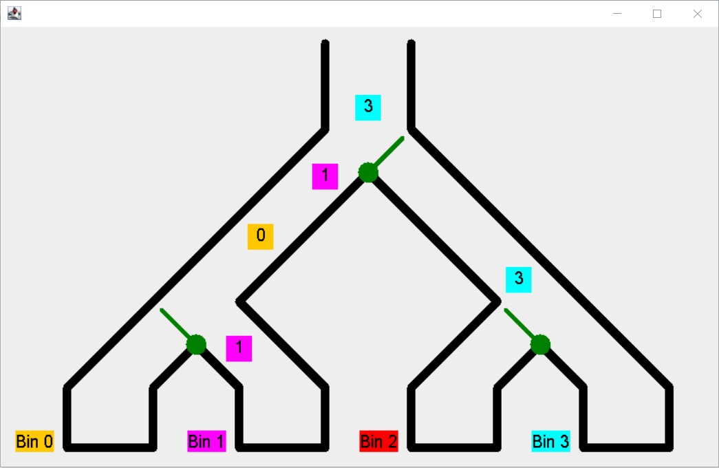
    To use the animation, it must be invoked first by right-clicking the 'ParcelRouterAnimation' Java project in the Project Explorer, selecting 'Run As' and then 'Java Application'. Note that:


  5. Problems in the current model:
    The provided model has two problems:
    1. Problem 1 (Lost parcels): When a parcel is generated or has reached the end of a chute or a switcher, the model currently passes on the parcel regardless of whether or not the next unit (i.e., chute, switcher, or bin) is empty and can actually hold that parcel. As a consequence, parcels appear to 'get lost' under certain delay settings. Problematic settings are those which cause a unit to receive a new parcel before the current one has been passed on. Examples are

      >> ./Parcelrouter.exe -UARGS 10 1 2 1 0
      >> ./Parcelrouter.exe -UARGS 10 0 1 0 2

      which, in my implementation, cause 5 and 9 parcels to get lost respectively. Lost parcels will manifest themselves in the execution as 'unexpected messages' preventing it from running to completion. Similarly, the animation will become inconsistent. Note that not all delay settings are problematic. E.g., using

      >> ./Parcelrouter.exe -UARGS 10 1 0 0 0
      >> ./Parcelrouter.exe -UARGS 10 2 1 1 0
      >> ./Parcelrouter.exe -UARGS 10 3 0 1 1

      no parcels get lost.

    2. Problem 2 (Incorrect routing): The model currently routes all parcels to just one bin which is obviously incorrect. Both, the console output and the animation show this. E.g., the console output of the execution of

      >> ./Parcelrouter.exe -UARGS 10 3 0 1 1

      ends in

      [ParcelR] total generations: 4 2 1 3
      [ParcelR] total correct arrivals: 4 0 0 0, total incorrect arrivals: 6
      [ParcelR] delay settings: 3 0 1 1
      [ParcelR] duration: 34 sec, 143997000 nsec
      [ParcelR] stop

    While the animation output is useful for many (non-zero) delay settings, due to the limitations of the animation mentioned above, the console output is, in general, better suited to tell you if an execution exhibited one of the two problems above.

  6. Task description

Part II (5 points total)

  1. Problem Description:
    We now briefly return to the problem of giving change discussed earlier. We observe the following about all three designs in Part II of Assignment 2: These observations motivate the next design of the changer capsule:

    Capsule diagram of Verion 4 of Changer capsule

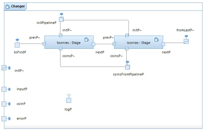
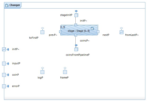
    In this design, each of the two coin denominations has its own capsule instance (called 'toonies' and 'loonies'). These instances are connected to form the stages of a pipeline in which:

    This design now shows us how to come up with a fully general solution, i.e., a version of the changer that is parametric in the number of coins that are used for giving change and their respective denominations. For example, we want the invocation

    	$ ./executable.exe -URTS_DEBUG=quit -UARGS  81 400 200 100 10 1      
    to dispense one 200-cent coin, one 100-cent coin, one 10-cent coin, and nine 1-cent coins. That is, on the command line, the value of the selected item and the amount of money inserted is followed by a monotonically decreasing list of integers indicating the denominations of the coins to use (the number of coins is given by the length of this list):
    	$ ./executable.exe -URTS_DEBUG=quit -UARGS  <ins> <sel> <denomination of highest value coin> ... <denomination of lowest value coin>      
    For this to be possible, the pipeline needs to be built dynamically (i.e., at runtime) according to the command line arguments provided. E.g., in the invocation above
    The last design (GiveChangeV5) implements this using the following UML-RT features: Also, instead of sending the denomination to each stage via an initialization message, this information is provided by the changer to the instance as an argument to the 'incarnate' function. Note how the capsule diagram of the Changer capsule does not show the pipeline (because its shape (length) is unknown prior to runtime), but does show that the stage instances are optional and that their pipeline ports 'prevP' and nextP' are unwired at the start (and, thus, wired dynamically).

    Capsule diagram of Verion 5 of Changer capsule

  2. Task description:
    Import and build the model realizing this fully general process of giving change (GiveChangeV5_forA3.zip). Consider the system execution caused by the following invocation:
          $ ./executable.exe -URTS_DEBUG=quit -UARGS 1575 2000 200 100 10 5    
    Execute and inspect the model to understand the resulting execution. Draw a sequence diagram showing all the messages exchanged between all capsule instances (i.e., 'Top', 'harness', 'changer', and all pipeline stages) as a result of this invocation. Your diagram should also include calls to the 'incarnate' function, if any. If messages or calls to 'incarnate' carry data, please include them as well.

    Put your sequence diagram into your parcel router project from Part I and give it the name Part2.

What to hand in:

Marking:

For Tasks 2 and 3 of Part I, your changes to the model will be marked based on their correctness and completeness (with respect to the assignment instructions and the system descripion), but also using the design guidelines discussed in class. Your answer to Task 4 be marked on completeness, precision and clarity.


Last modified: Wed Oct 20 2021 14:54:58